Wednesday 22 October 2008

Using the Light Lister and Ram Player


In order to see what lighting you have in a scene a really useful tool is the light lister. You will find this under tools > Light lister. Here you can change the listed parameters without having to enter the modify panel and you can keep the lister up on your desktop for easy viewing.


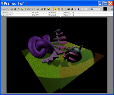
Another very useful tool is the RAM Player. This allows you to render two images and load them into the player. This is ideal when you are tweeking the lighting in your scene. Sometimes the changes are very subtle, and therefore the ram player allows you to toggle between the two renders to see the changes.


Go to Rendering > RAM player, and up pops the Player on the desktop. In Channel A, click on the small green teapot, which will allow you to load your last render. I have changed the colour of the spotlight and then re-rendered the image. In Channel B load the newly rendered image. Now you can see the two renders, and can move the small slider along to see the difference in the renders.


Basic Lighting - Spotlights, Directional and Omni Lights


Max has two default lights in the viewports which enable the user to see their models in a basically lit environment. As soon as you start to add your own lighting, that default changes, and Max updates the view to whatever lighting that you specifiy.


Make a small scene, click and drag a plane in the perspective viewport and place assorted standard and extended primitives on that plane, so that you can test out the different lights.


Go to the Creat panel, and click on the small lighting symbol. In the Front viewport click and drag a target spot.


In order to see your lighting update it is a good idea to change one of the viewports to Perspective view - Active Shade - Spot.


Target Spotlights are very useful for mood lighting, free target spots can be used for car headlamps, streetlamps etc. A potlight illuminates an area within a cone, similar to a stage light. Target Spotlights point at a target that you aim, whereas freww spotlights are taargetless, so they can be moved easily. You can align a target light to a path and animate it if you wanted to.


With your target spotlight highlighted, go to the modify panel, and it will reveal a target spotlight rollout.


Under general parameters, you can change the light to either an Omni light or Directional light. An Omni light radiates light in all directions and is ideal for general sunlight, or an overhead light in a room, the light radiates from the one source. Directional lights use a cone of illumination and the sides of the cone are parallel rather than radiating from a single source like spotlights.


You will also notice that you can add shadows. Just check the box next to shadow and miraculously you will get shadows within your scene. Here you can specify different shadow types using different rendering techniques , which will be covered next semester.


In the next box you will find Intensity/Colour Attenuation. Here you can change the intesity of the light by changing the Multiplier spinner, and if you click on the colour square you can change the colour of the light. Here I have changed the colour of the light to light blue, and have added an extra target spot to illuminate the scene even more so that you can see the changes.


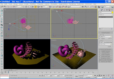
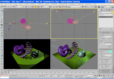
You can also change the attenution, but again this will be covered next semester. You can change your spotlight from a round stagelight to a square light in the spotlight parameters box.

In Advanced effects you can add a map to your spotlight. Check the projector map box and click on the map box to add either a proceedural map or one of your own. I have added a speckle map to mine and here is the effect it provides. 
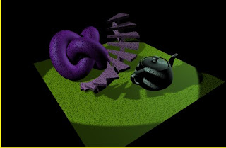
Omni lights and Directional lights have the same rollouts and parameters, so it is a good idea to play with these to see what sort of lighting effects that you can produce.


Wednesday 8 October 2008

Tutorial 9 - Producing a reflective material


  1. In the Create panel go to Extended primitives. Click and drag a torus knot in the perspective viewport.
  2. Open the Material Editor. Pick an Anastropic shader as this is ideal for metal materials. Check on the diffuse button and change the colour to a dark blue. Make sure that you have a high specular level approx 60 and a high anastrophy approx 80.
  3. Navigate to the maps rollout further down the panel, Click on Reflection > None and click on Material Library. In the Material library there should be some environmental maps - pick a scene such as Hong Kong. This will now add the Hong Kong image to the reflective map channel.
  4. Drag the material from the slot to the torus knot.

Tutorial 8 - Material ID and Multi/Sub Object Proceedural Map


This technique is great when you have a poly model that requires different materials - such as a character wearing clothes.
  1. Click and drag a teapot into the perspective viewport.
  2. Convert the teapot to an editable poly.
  3. In the modify panel, check element.
  4. Scroll down to polygon properties to Material ID
  5. Click on the teapot spout and allocate ID 1
  6. Click on the lid and allocate ID 2
  7. Click on the belly of the teapot and allocate ID 3
  8. Click on the handle and allocate ID 4
  9. Come out of editable poly.
  10. Open the material editor.
  11. Click on Standard to pull up the proceedural map menu > choose Multi/sub object material > OK.
  12. You now have 10 material slots. You add materials or maps to the first four slots. Click on Material#standard and either add a map or make your own material. You then see these materials in the sample slot.
  13. Click and drag the sample slot material to the teapot and the different materials are automatically assigned to the different elements of the teapot.

Friday 26 September 2008

Tutorial 7 - Making your own materials


In order to make your own materials to import into 3DS Max, you need to use Photoshop.


Make a new file, approx 3cm x 3cm. Using the brush, make a random pattern within the file. Save as a bitmap.


In 3DS Max, click on the Material Editor. Click on a slot and got to the diffuse slot. Next to the slot is a small box. Click on this and it reveals the material editor. At the top of the material editor is Bitmap. Click on Bitmap, and a dialogue box appears to allow you to find the image you made in Photoshop. The image will appear in the material slot. Click and drag it to your object.


Tutorial 6 - Materials - Shaders


In order to start making materials you have to chose the relevent shader to make that material.


Anastropic


The anastropic shader is ideal for metal materials, because it changes the shape of the specular from round to elongated via the anastrophy spinner. You can also change the direction of the shine. It works very well for hair where the shaft of the hair catches the light.


Blinn


This is the standard Max default - A basic shader which can be used for most materials, it has a no anastrophy.


Metal


This was in use until the Anastropic shader was introduced, it is more simple in the way it works, there is a dimple in the specular graph, which means that the shader is useful for dull metal materials such as brushed stainless steel.


Muli-layer


This is very good for metalic objects, particularly cars, as it has two layers of specularity. You can also change the colours of the specular layer to add subtle tones.


Orin-Nayer-Blinn

This is much softer in tone than Blinn and produces a very soft feel to the material. It is ideal for organic materials such as skin, velvet, as it slightly absorbs light.


Phong

This is one of the original shaders and is not really used anymore. Gives a plastic feel to a material.


Strauss

This is good for plastic, or can be used for metal, but there are not a lot of parametres and is not utilised much.


Translucent

This is a fun shader - and can be used to produce psychodelic influences on the material, glowing effects etc. It offers translucency, and opacity plus filter colour.


Monday 8 September 2008

Tutorial 5 - Rendering your scene


To render your calendar scene

Click on Render in the top tool bar, or click on the Render button, an icon, which looks like a teapot with a blue and white box.
The Render dialogue box will appear.
As we are rendering a still image we need to check “Single” in the “Time output” box.

Output size – check 640 X 480

Scroll down to Render output > Files, and select the area you wish to save your file.
Save as type BMP or JPEG, and press SAVE.
In the Render Scene dialogue click on RENDER, and the image will be rendered to your file.

Tutorial 4a - Producing a Circular Array


Producing a Circular Array

Click and drag a teapot into the perspective viewport.
Click the Use Pivot Point Centre button on the main toolbar and drag down to the last icon, which is the Use Transform Coordinate Centre button.
Make sure the teapot is highlighted.
Go to Tools > Array for the Array dialogue box.
Between the Incremental and Totals sections are the labels “Move”, “Rotate” and “Scale”. Click the arrow button to the right of the rotate label. Set the axis which you would like to rotate the teapot and type in 360 degrees.
In the Array dimensions section, set the 1D spinner count value to 6 and click the OK button to create the array.

Tutorial 4 - Making a Linear Array


Producing a Linear Array

Make a shape like a piece of picket fencing in the perspective viewport. Make sure this is highlighted.
Go to Tools > Array and this opens an array dialogue box.
Make sure that the Preview button is checked

In array dimensions, check 2D, and in the Count select how many copies of the fence post you require. Then click on the X spinner. You can now see the fence post being cloned. Take the X spinner up to 25.

Now check 3D, and choosing the Y spinner, you will see the set of fence posts being cloned, take the spinner again up to 25.


Friday 5 September 2008

Tutorial 3 a - Using the Loft tool


Modelling a coat hanger using Loft

In the front viewport, using the line spline tool, draw out the shape of a coat hanger.

Also in the front viewport, click and drag a small circle (spline)

Go to Creat > Compound Objects > Loft.

Make sure that the coat hanger spline is highlighted, and then in the Loft properties box, click on get shape, and then click on the circle.

You now have a complete coat hanger.

Tutorial 3 - Booleans and Pro-boolean


Modelling using Boolean and Pro Boolean

Create a large flat box.
Now create a letter from Spline text. Turn the spline into an editable poly. Extrude the letter so that it is deeper than the box and cap the end.
Place the letter in the middle of the box so that it intersects it.
Go to Create > Compound objects > Boolean
In the Boolean parameters it will tell you that the box is operand A. Click the Pick Operand B button and choose the letter as Operand B. In the properties dialogue you with to subtract B from A.
Now you have an letter shaped Boolean through your box.
If you have more than one shape that you wish to boolean, use the pro-boolean tool which asks you to keep picking operand B until all the shapes are removed.

Tutorial 2a Modelling with Splines


Lathing with Splines – Making a bowl.

Go to the create panel > shapes

Using the line tool, set Initial type and Drag type to smooth – this will provide you with a curved line.

Click and drag your shape in the Front viewport.

When you have produced your shape, you need to change the pivot point from the centre of the shape to the base of the shape so that the lathe modifier rotates around the base of the bowl. Navigate to the modify panel/list, pick the lathe modifier.
This will automatically lathe around the Y axis, but you can change this if needs be in the lathe properties panel.

Tutorial 2 - Modelling with splines


Modelling with splines – producing an S shaped beam

Creating splines is a way of drawing out a shape initially and then either editing the spline to make it 3D or applying a modifier.

Go to the create panel > shapes

Using the line tool, set Initial type and Drag type to smooth – this will provide you with a curved line.

Click and drag your shape in the Front viewport.

When you have produced your S shape right click on the spline, and convert to editable poly.

Use the extrude tool to pull the shape out into a beam. You will see that the 3D shape has a front normal and a side normal but no back face.

In the Editable Spine rollout, pick Border, and click on the border of the open edge. In the rollout pick Cap. This now provides you with an editable 3D shape.

To make a banana


To make a banana

Click and drag a box into the perspective viewport.
Go to sub-object level, and using the extrude and bevel tools gradually build up the tapering shape of a banana.

Then using soft selection tweak the banana to make the shape more random.
When you are happy with the shape try using the meshsmooth or turbosmooth modifier to reveal a more organic shape.


To produce an apple

Click and drag a sphere into the perspective viewport
Go into sub-object level, and enter the Soft Selection part of the Editable Poly rollout.
Using soft selection and vertices, you can alter the shape of the sphere to represent a typical apple. The shape should be fairly random – no apples are completely perfect and round!

Still in Soft selection select the top vertex of your apple shape and drag the cursor down to produce the dent in which the stalk sits.

If you are going for total realism, pull out some bumps at the bottom of the apple.

Next add a stalk, which can be achieved using an elongated cone, placed in the top of the apple. Add a leaf if you like.

Tuesday 26 August 2008

The Brief


The Brief for Semester 1

Seasonal Calendar


Calendars have multiple uses; as an aid memoire, as a form of decoration, a personal statement, and even a form of promotion. These days there are many variations of calendar, from the sayings of George Bush, promotion of the local Indian takeaway to different types of dog.
You are to produce three 3D still images to represent three different months of the year of your choice. What is it that you associate with those months? What is the weather like? What seasonal holidays occur? What types of flowers are in bloom etc? The images you produce should be an evocative representation of that time of the year.


The Brief for Semester 2

Programme Identity

Corporate identity is vital in today’s fast changing and competitive environment, particularly in television, where many different companies battle to improve their ratings. Broadcasting companies have had a corporate style since television began, but since the advent of cable and digital television, corporate image has come to the fore, with a plethora of different broadcasting companies vying for recognition and status. Campaigns which used to change yearly are now changing season to season, month to month.
The most recent memorable ident campaigns are those for BBC1, BBC 2 and Channel 4.

So why are corporate idents needed?

They provides a breathing space between programmes
They allow for announcements between programmes
They orientate and remind viewers which broadcasting company they are watching
They are increasingly eye catching and creative in order to capture the viewer’s imagination, so that the company is advertised through word of mouth.
Promotion of the company


Using 3D Studio Max, you are to produce a set of three idents to promote a channel of your choice. The idents should be innovative and imaginative, and actively celebrate the ethos of the corporation that they represent.